Battery Management System Settings
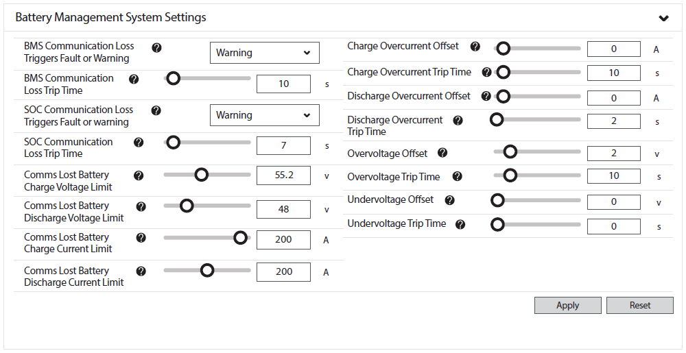
InsightLocal > Devices > Inverter/Charger > Configuration (Advanced) > Battery Management System Settings
Battery Management System Settings
|
InsightLocal > Battery Management System Settings |
Description |
|---|---|
|
BMS Communication Loss Triggers Fault or Warning (Fault, Warning) |
Set the preferred response of XW PRO when communication is lost with the Battery Management System (BMS).
|
|
BMS Communication Loss Trip Time (Seconds) |
Default: 10 seconds. This property specifies the delay before a fault or warning is triggered after losing communication with the BMS. |
|
SOC Communication Loss Triggers Fault or Warning (Fault, Warning) |
Set the preferred inverter response when there is a loss of State of Charge (SOC) communications.
|
|
SOC Communication Loss Trip Time (Seconds) |
Default: 7 seconds. This is the delay before a fault or warning is triggered after losing SOC Communication. |
|
Comms Lost Battery Charge Voltage Limit (V) |
When a Discover battery is selected in BMS Setup, XW PRO defaults to 54.4 V when Comms Lost (Open-loop). This value is used if BMS or battery SOC communication is lost. |
|
Comms Lost Battery Discharge Voltage Limit (V) |
|
|
Comms Lost Battery Charge Current Limit (A) |
When a Discover battery is selected in BMS Setup and when Comms Lost (Open-loop), XW PRO defaults to:
NOTE:
|
|
Comms Lost Battery Discharge Current Limit (A) |
|
|
Charge Overcurrent Offset (A) |
Default: 0 A. When Charge Cycle is set to External BMS, the offset is added to the charge overcurrent limit broadcast by the BMS (or the Comms Lost Charge Current Limit) to determine the inverter’s trip threshold. When operating off-grid with AC coupling enabled, the inverter follows the BMS charge current limit by frequency-shifting AC-coupled PV. The inverter triggers fault F73 if the current exceeds the trip threshold for the number of seconds specified in the Charge Overcurrent Trip Time property. |
|
Charge Overcurrent Trip Time (Seconds) |
Default: 10 seconds. A F73 fault is triggered after the Charge Overcurrent trip threshold is exceeded (refer to Charge Overcurrent Offset) and the specified time elapses. |
|
Discharge Overcurrent Offset (A) |
Default: 0 A. When Charge Cycle is set to External BMS, the offset is added to the discharge current limit broadcast by the BMS (or the Comms Lost Battery Discharge Current Limit) to determine the inverter’s trip threshold. When operating off-grid, the inverter follows the loads until it hits the trip threshold. The inverter triggers fault F71 if the current exceeds the trip threshold for the number of seconds specified in the Discharge Overcurrent Trip Time property. |
|
Discharge Overcurrent Trip Time (Seconds) |
Default: 2 seconds. A F71 fault is triggered after the Discharge Overcurrent trip threshold is exceeded (refer to Discharge Overcurrent Offset) and the specified time elapses. |
|
Overvoltage Offset (V) |
Recommended: 2.0 V. Default: 0.5 V. When the Charge Cycle is set to External BMS, the offset is added to the charge voltage limit broadcast by the BMS (or the Comms Lost Charge Voltage Limit) to determine the inverter’s trip threshold. The inverter triggers fault F75 if the voltage exceeds the trip threshold for the number of seconds specified in the Overvoltage Trip Time property. |
|
Overvoltage Trip Time (Seconds) |
Default: 10 seconds. A F75 fault is triggered after the Overvoltage trip threshold is exceeded (refer to Discharge Overcurrent Offset) and the specified time elapses. |
|
Undervoltage Offset (V) |
Default: 0 V. When Charge Cycle is set to External BMS, the offset is subtracted from the discharge voltage limit broadcast by the BMS (or the Comms Lost Discharge Voltage Limit) to determine the inverter’s trip threshold. The inverter triggers fault F74 if the voltage falls below the trip threshold for the time specified by the Undervoltage Trip Time property. |
|
Undervoltage Trip Time (Seconds) |
Default: 0 seconds. A F74 fault is triggered after the battery voltage falls below the trip threshold (refer to Undervoltage Offset) and the specified time elapses. |
Battery Settings
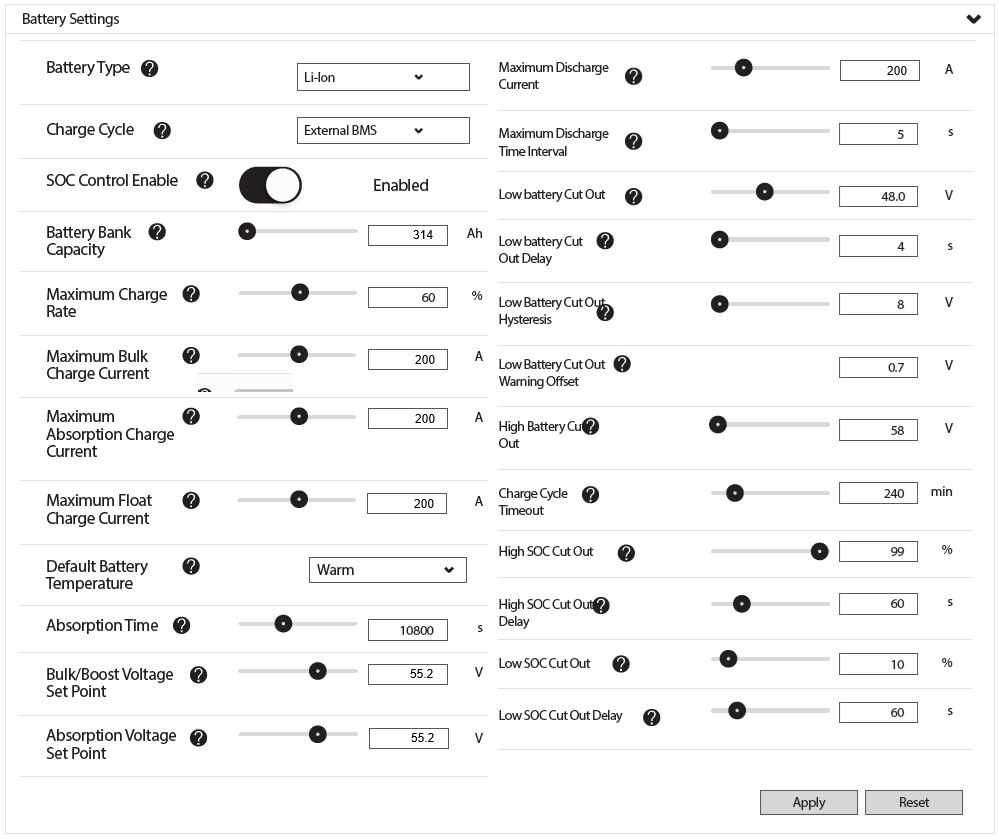
InsightLocal > Devices > Inverter/Chargers > Configuration (Advanced) > Battery Settings
|
InsightLocal > Battery Settings |
Description |
|---|---|
|
Battery Type (Flooded, GEL, AGM, Custom, Li-ion) |
Default: Li-ion. |
|
Charge Cycle (3 Stage, 2 Stage, External BMS) |
Default: External BMS. |
|
SOC Control Enable (Enabled/Disabled) |
Default: Enabled. |
|
Battery Bank Capacity (Ah) |
This value must be set to the number of batteries in the system multiplied by the rated capacity of the Discover Lithium battery.
|
|
Maximum Charge Rate (%) |
If required, use this setting to de-rate the charger output of each device in the system (i.e., This is not a system-wide setting). The maximum charging current delivered by the entire system should not exceed the maximum charge current rating of the entire battery system. |
|
Maximum Bulk Charge Current (A) |
In a closed-loop system, the BMS programs this property. Configure these values in case BMS communication is lost and the inverter operates in open loop. Refer to Schneider Electric Open-Loop Configuration. |
|
Maximum Absorption Charge Current (A) |
|
|
Maximum Float Charge Current (A) |
|
|
Default Battery Temperature (Hot, Warm, Cold) |
In a closed-loop system, the BMS programs this property. When Comms Lost (open loop), this setting is defaulted to Warm. |
|
Absorption Time (Seconds) |
In a closed-loop system, the BMS programs this property. When Comms Lost (open loop), this setting is defaulted to 10800 seconds (3.0 Hr). |
|
Bulk/Boost Voltage Set Point (V) |
In a closed-loop system, the BMS programs this property. Configure these values to 55.2 V in case BMS communication is lost and the inverter operates in open loop. Refer to Schneider Electric Open-Loop Configuration. |
|
Absorption Voltage Set Point (V) |
|
|
Maximum Discharge Current (A) |
In a closed-loop system, the BMS programs this property. Set the maximum discharge current when operating the inverter in open loop.
|
|
Maximum Discharge Time Interval (Seconds) |
When using a single battery, this value defaults to 8 seconds. You can set a higher value when using multiple batteries. |
|
Low Battery Cut Out (V) |
In a closed-loop system, the BMS programs this property. Default: 48 V. |
|
Low Battery Cut-Out Delay (Seconds) |
Recommended: 10 seconds or less. Setting the Low Battery Cut Out Delay avoids unnecessary engagement of the BMS. |
|
Low Battery Cut Out Hysteresis (V) |
In a closed-loop system, the BMS programs this property. Default: 2 V. |
|
Low Battery Cut Out Warning Offset (V) |
|
|
High Battery Cut Out (V) |
In a closed-loop system, the BMS programs this property. |
|
Charge Cycle Timeout (Minutes) |
This setting is for use when operating in Comms Lost (Open-loop). Default: 240 minutes. |
|
High SOC Cut Out (%) |
Default: 99% when operating in closed loop.
|
|
High SOC Cut-Out Delay (Seconds) |
Default: 60 seconds when operating in closed loop. |
|
Low SOC Cut Out (%) |
Default: 10% when operating in closed loop. Although the battery can be discharged to 100% Depth of Discharge, it must be recharged immediately to avoid cell damage. An over-discharged battery may be unable to accept a charge and become unrecoverable. |
|
Low SOC Cut-Out Delay (Seconds) |
Default: 60 seconds when operating in closed loop. |
Charger Settings
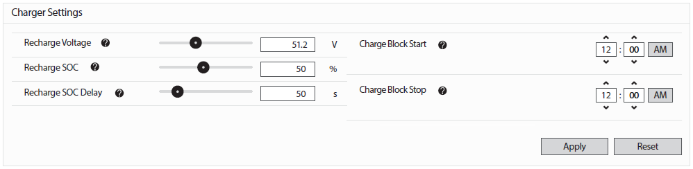
InsightLocal > Devices > Inverter/Chargers > Configuration (Advanced) > Charger Settings
|
InsightLocal > Charger Settings |
Description |
|---|---|
|
Recharge Voltage (V) |
XW PRO defaults to using SOC to trigger when to recharge in a closed-loop system. Set the battery voltage at which recharging begins when Comms Lost (Open Loop). The default is 51.2 V. |
|
Recharge SOC (%) |
Specifies the amount of energy to keep in reserve for backup. Setting a lower SOC enables a higher level of self-consumption. |
|
Recharge SOC Delay (seconds) |
Specifies the amount of delay before recharging. |
|
Charge Block Start Charge Block Stop |
Charge Block specifies when AC charging from the grid is blocked. Specify the time range when AC charging is blocked. |